The Recent Update of a Powerful Specification
September 15, 2020
Story

SMARC 2.0 modules stand out thanks to their large number of graphics, camera, sound, network and optional wireless interfaces.
SMARC 2.0 modules stand out thanks to their large number of graphics, camera, sound, network and optional wireless interfaces. They therefore offer embedded system developers a complete, off-the-shelf, credit-card-sized embedded computing core that is ideal for both IoT connected multimedia platforms as well as many other graphics-intensive low-power applications. The updated specification SMARC 2.1 extends this feature set even further.
More camera interfaces demanded
Current studies[i] by Industry Research.co show that the demand for machine vision cameras is growing at double-digit rates. Growth is particularly strong in various non-industrial applications such as surveillance, forensics, robotic surgery, intelligent traffic systems, border control, and health monitoring. In addition, camera technology continues to be used for process inspections to reduce errors such as incorrect fill levels, faulty products in the production line and packaging defects. Autonomous logistics vehicles also take up a large market share in the industrial sector. The new SMARC 2.1 specification adapts to this demand. Thus, SMARC 2.1 is an important step towards firmly embedding MIPI-CSI camera technology (which is widely used in smartphones) within the standard of an embedded computing specification for the first time.
Quad MIPI CSI interfaces
The new revision brings numerous additional features as well. Firstly, SMARC 2.1 defines two additional MIPI CSI interfaces on flat foil connectors on the module surface. There are already two MIPI CSI interfaces on the module connectors. It is now possible to connect up to a total of 4 MIPI CSI cameras for sophisticated vision applications. Both new MIPI CSI Interfaces support 4 differential pairs of data lines to provide the required data throughput for high resolution cameras with fast frame rates. The first interface available on the module edge connector supports two data line pairs, and the second one supports four. All four camera interfaces can be implemented according to both the MIPI CSI 2.0 specification as well as the newer MIPI CSI 3.0 specification. In addition to a higher data rate, version 3.0 uses a differential line pair instead of an I²C bus to configure the connected cameras. Additional cameras can be connected by USB or Ethernet interfaces.
Extended connectivity
With connectivity at the edge gaining increasing significance, two of the 4 PCI Express lanes (PCIe C & PCIe D) can now be used alternatively as SERDES interfaces to provide additional Ethernet functionality. To configure required PHYs on the carrier board, an additional MDIO interface was created at previously reserved module pins. In combination with the two fixed defined Ethernet ports, a solution with up to 4x gigabits of Ethernet can now be realized. They can also be used for vision by connecting GigE vision cameras.
Additional GPIOs
SMARC 2.1 also increases the number of GPIOs from 12 to 14 pins. Both new IOs are located at previously reserved pins. Since the first 7 GPIOs are often already used for other, frequently required functions (see table below), SMARC 2.1 provides at least seven truly free GPIOs.

(Figure 1: The main changes in the SMARC 2.1 specification are extended Ethernet and MIPI camera connectivity)
PCI Express power saving mode
The first two PCI Express lanes are equipped with additional clock request signals in SMARC 2.1. This makes it possible to switch off the individual PCI Express interfaces to save energy, which is especially important for mobile, battery powered devices.
All SPI possibilities
In addition to SPI and eSPI, SMARC 2.1 also provides the option of implementing QSPI. This extended version of the SPI interface is often used with ARM processors. The difference between SPI and QSPI is that the former uses a data queue with programmable queue pointers to allow data transfers without CPU intervention. The wrap-around mode allows continuous transfers out of the queue without CPU intervention. The peripherals appear to the CPU as parallel devices with memory mappings. This is especially useful for applications with analog-to-digital converters. SMARC 2.1 allows for alternative implementations of SPI, eSPI and QSPI.
Full backward compatibility with SMARC 2.0
Since all new features have been implemented as alternative functions to existing signals and/or on unused pins, SMARC 2.0 is 100% backward compatible. This means that 2.1 modules can be integrated on 2.0 carriers. All extensions to Rev.2.0 are also optional, so all congatec SMARC 2.0 modules are automatically compatible with SMARC 2.1. Consequently, it is only necessary to redesign existing SMARC 2.0 carrier boards if new SMARC 2.1 functions are used. Moreover, in response to many requests, the specification document has also been completely revised to optimize readability.

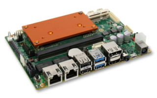
(Figure 2: congatec offers a 3.5” carrier board with a slot for SMARC Computer-on-Modules. For ARM designs, it is scalable in 12 performance levels, from the most powerful i.MX 8QuadMax processor to i.MX 8 M mini processors in 14nm technology. A corresponding x86 carrier is also available, offering a different audio codec.)
The specification was developed by SDT.01 (Standards Development Team) within SGET. The specification is freely available on the SGET website (www.sget.org). A freely available Carrier Board Design Guide for SMARC can also be found on the SGET website (www.sget.org). Using many reusable schematic examples, this document shows how carrier boards can be developed quickly and easily. In addition, congatec offers a new 3.5” carrier board that can be equipped with all different Arm and x86-based SMARC modules from congatec. OEMs can use it not only as an evaluation platform but also as a highly scalable off-the-shelf platform solution that is available in series production and instantly deployable even with the first batch.


