Getting Started with MIPI I3C: A Guide for System Designers
July 27, 2026
Blog
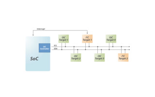
As system designs grow more complex in mobile, automotive and IoT applications, there’s a need to connect more advanced sensors and peripherals while reducing power, pin count and latency. That’s where MIPI I3C comes in.
MIPI I3C is a two-wire serial interface that combines the simplicity of legacy approaches with significantly higher efficiency and performance gains. It delivers typical speeds of around 11 Mbps in single data rate (SDR) mode—with options up to 100 Mbps—while maintaining low power consumption and backward compatibility with I²C devices.
A Faster, More Efficient Two-Wire-Based Interface
Not only does MIPI I3C offer faster speeds, but it also introduces several architectural improvements that simplify system design:
- Dynamic addressing eliminates fixed address conflicts
- In-band interrupts remove the need for extra GPIO lines
- Hot-join allows devices to be added after initialization
- High data rate (HDR) modes enable burst transfers
- Highly accurate time-stamping supports sensor fusion
- Advanced power management enables sleep modes
These features allow a single I3C bus to handle control, data transport, and system management more efficiently than legacy interfaces (Table 1.)
|
Feature |
MIPI I3C |
I2C |
SPI |
|
Type |
Advanced multi-drop bus |
Multi-drop bus |
Point-to-point / multi-target |
|
Wires/Pins (Typical) |
2 (SCL, SDA) |
2 (SCL, SDA) + GPIOs |
3 (SCLK, MOSI, MISO) plus 1 CS per device |
|
Data rate (Standard Mode) |
~11 Mbps (SDR) |
Up to 100 Kbps (Standard Mode) |
10 to 100+ Mbps |
|
Data rate (Advanced Modes) |
Up to 100 Mbps with HDR multi-channel modes |
Up to 3.4 Mbps with HS mode |
N/A |
|
Topology |
Shared bus with dynamic addressing |
Shared bus |
Star (separate CS lines per slave) |
|
Addressing |
Dynamic + static |
Static |
N/A (uses chip select lines) |
|
In-band Interrupts |
Yes |
No (requires extra wires) |
No (requires extra wires) |
|
Power Consumption |
Low (push-pull, more efficient) |
Higher (open-drain, pull-ups) |
Low (push-pull) |
|
Backward Compatibility |
Coexistence with I2C devices |
N/A |
N/A |
|
Hot-join |
Yes |
No |
No |
|
Multi-controller support |
Improved |
Limited |
No |
|
Error handling |
Enhanced error detection |
Basic ACK/NACK |
None |
Table 1. Comparison of features between I3C, I2C and SPI.
Current and Emerging Use Cases
MIPI I3C is quickly becoming a foundational technology powering the next generation of high-performance products across enterprise, consumer and IoT markets. Example use cases are numerous.
In consumer AR headsets, the interface is enabling faster, more accurate sensor fusion over a single, shared two-wire bus, where lower-power, compact implementation is critical for small battery-powered devices measuring motion, environmental and biological signals.
In enterprise computing, JEDEC has adopted the use of MIPI I3C for DDR5 serial presence detect, power and temperature management, superseding the use of legacy I²C to enable faster, more efficient and scalable memory-module management. Additionally, I3C has been adopted by PCI-SIG for NVMe-MI sideband communication and the use of MCTP protocols on top of I3C.
The I3C interface for ETSI SSP (ETSI TS 103 818) and UICC (TS 102 412) adds I3C Basic as one of the possible physical interfaces, in addition to I2C, SPI, and ISO 7816. Thanks to the multidrop configuration of the MIPI I3C bus, the SSP and UICC will become accessible to all devices connected to the bus that can benefit from security services that the SSP may offer.
In IoT applications, I3C is enabling low-power, always-on sensing by connecting I3C-enabled cameras and 3D time-of-flight sensors with low-cost MCUs, supporting efficient battery-powered operation.
A future use case for I3C, being developed by the MIPI I/O Bridges Working Group, will enable I3C to be used as an I/O bridge, a pin-saving device that enables multiple legacy I/O signals (i.e., GPIOs, SPIs, I2C interfaces) to be aggregated over a single I3C interface—ideal for systems where there is a need to route multiple legacy interfaces though a complex hinge mechanism or other physically constrained environments.
Get Started with the Basics
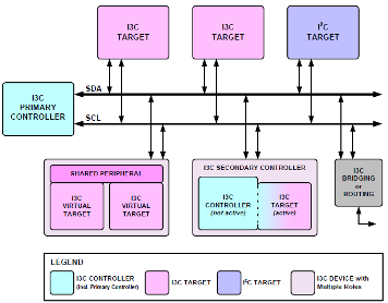
If you’re new to MIPI I3C, a good starting place is with I3C Basic, the publicly available version of the specification. It includes the most commonly used features and essential functionality to satisfy the technical requirements of the vast majority of system designs, providing a practical entry point for developers and offering a clear upgrade path to the full I3C specification if necessary.
Reviewing the specification and accompanying application notes will provide a solid understanding of the bus structure, command codes and device roles.
Choose the Right Hardware, Software and Tools
Getting started with I3C requires compatible hardware, software and tools. The rapidly growing ecosystem offers a range of microcontrollers and microprocessors, sensors and peripherals, development boards and evaluation kits—all designed for MIPI I3C.
Many vendors now offer reference designs, code examples and driver support to accelerate development. Starting with a development kit can significantly reduce setup time and help you validate your design early.
To support developers, MIPI has provided several software-enabling specifications to facilitate the integration of MIPI I3C: Discovery and Configuration (MIPI DisCo for I3C), I3C Host Controller Interface (MIPI I3C HCI) and Transfer Command Response Interface (MIPI I3C TCRI), all publicly available. An I3C HCI driver is also available in the Linux kernel.
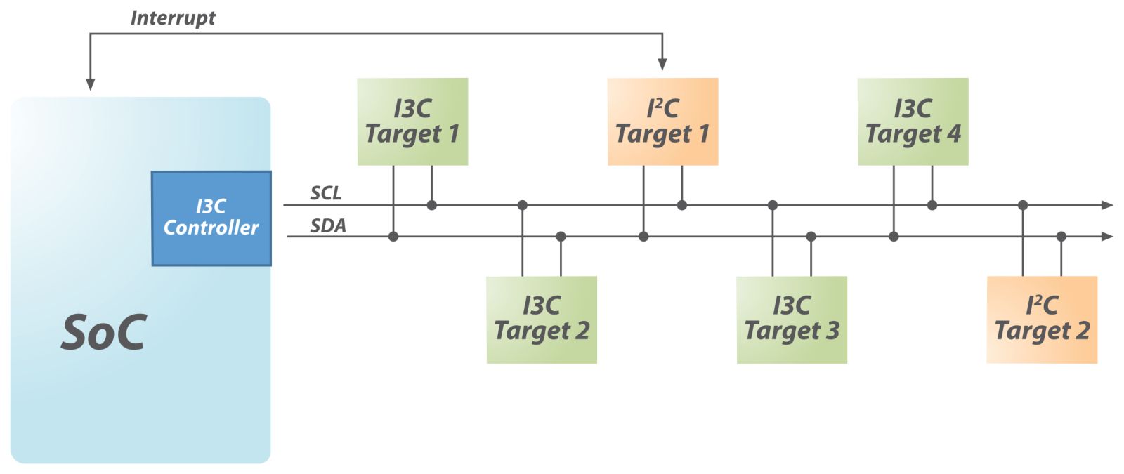
Build and Validate a Prototype
Once you have hardware and software in place, the next step is to build a simple prototype:
- Connect a controller to one or more I3C targets
- Configure dynamic address assignment or set static addresses
- Test basic read/write transactions
- Experiment with features such as in-band interrupts and hot-join
At this stage, focus on validating core communication and ensuring signal integrity. Because I3C is typically used for on-board communication, proper PCB layout and short trace lengths are important for reliable performance.
For early experimentation, tools like the open-source I3C Blaster can help you prototype and analyze bus activity. These tools provide a practical way to explore transactions, debug communication, and understand timing behavior without building a full production system.
Plan for Migration and Scaling
One of I3C’s biggest advantages is its ability to coexist with I²C devices on the same bus, making it ideal for incremental adoption.
- Start with hybrid I²C/I3C systems
- Gradually replace legacy components when more performance is desired
- Scale up to full I3C implementations as needed
The flexibility of I3C allows developers to update designs without a complete redesign upfront.
Resources and Technical Support
For system designers looking to implement or transition to MIPI I3C, the MIPI Alliance offers an abundance of resources, including recently updated FAQs, a conformance test suite, and application notes. The organization also offers webinars and conference presentations, as well as plugfest events that provide hands-on testing opportunities for controllers and target devices.
Getting started with MIPI I3C is less about learning an entirely new paradigm and more about evolving legacy interfaces. With its combination of higher speed, lower power and smarter device management, I3C is well-positioned to become the default control and sensor interface for next-generation systems.