
Exploring the Low-Level MIDI Protocol with Arduino
July 02, 2024
Blog
MIDI (Musical Instrument Digital Interface) has been in use for roughly four decades as of this writing, and it is still going strong in the world of music production. As an engineer, I love a protocol that is designed to stand the test of time and features a robust connector–here a 5-pin connector formally known as a DIN 41524. Official specs are found here on MIDI.org under 5 PIN DIN ELECTRICAL SPECS.
If you’d like to implement MIDI on an Arduino, there is a handy library that makes things relatively straightforward. But if you want to understand this protocol on a deeper level, to the point where you can theoretically bit-bang a signal using direct pin high/low control and microsecond delays, in this article we’ll explore the MIDI protocol on a very low level.
MIDI Low-Level Protocol Basics (MIDI is UART)
MIDI messages come in several forms, but typically they consist of a status byte (what kind of message, which channel), followed by two data bytes that give information on the value of the MIDI message. Each byte is transmitted least-significant bit first, following the standard UART paradigm.
Elaborating further, each data byte (value) begins with either a 1 to signify that it is a status byte or a 0 to indicate that it is a data byte, leaving 7 bits for actual information, or values of between 0000000 and 1111111 or 0 and 127 in decimal. However, the value of an entire MIDI byte (with the 1 or 0 in front, ie. transmitted last) is between 0 and 127 in decimal (0 and 7F hex) for data bytes, and between 128 and 255 (80 and FF hex) for status bytes.
Actual messages are well covered elsewhere, but as an example, the MIDI command to play a C on the third octave of a keyboard is three bytes:
10010000 00111100 01111111 (binary) 90 3C 7F (hex)
Of note here is that C on third octave on a keyboard is 3C in hex. Whether this was a coincidence, or by design, I am not sure, but it’s a very nice frame of reference.
FINALLY, MIDI/UART lines are held in an electrically high (1) state when unused. Each byte starts with a low (0) bit and ends with a high (1) bit. This is taken care of in standard UART functionality, but at the physical layer, it is sending 10 signal changes for each byte of information. The standard MIDI baud rate is 31250, meaning .000032 seconds (32 microseconds) per transmission, or 10 times that per (8-bit) byte: 320 microseconds.
Image Credit: Screencap
Looking at the 90 3C 7F transmission sequence on a logic analyzer as shown above, note that the start (low) bit comes first, followed by the LSB to MSB of the 8-bit data set, followed by the high stop bit. So even though the data for the first byte is 10010000, the entirety of the byte is literally transmitted as the sequence “0-0-0-0-0-1-0-0-1-1.” Just take out the middle 8 bits, flip them, and you have a 1001000 binary/90 hex value. Simple… right? With the math sorted, let’s start programming!
The Hard Way To MIDI (Bit Banging)
To really test my understanding of this protocol, I wrote a bit-banged program to hit a C3 note on a keyboard over and over. It transmits a status byte, along with two data bytes, looping through each bit in a sequence. AI may have given me an assist with the code. Even so, this was finicky at best, and I used a Seeed XIAO SAMD21 to get it to inconsistently hit the correct note, while I used an Arduino Uno for much of my other testing.
I don’t recommend this method, but the process of writing this working-ish program helped with my MIDI understanding. Seeing it–available here on GitHub–may be instructive for you.
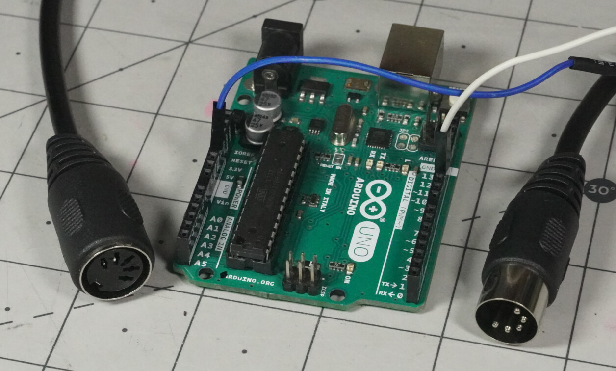
I’ll go over the hardware setup in a follow-up post, but for now, note that MIDI pin 4 is typically linked to a constant positive voltage (nominally +5V or +3.3V) via a resistor, and pin 5 goes to the microcontroller output. You can also check out the official MIDI document.
The Medium MIDI Method (UART)
With the challenging MIDI bit-bang operation out of the way, or at least understood, software serial UART should be a piece of cake. My code sends three MIDI command bytes in sequence without having to explicitly worry about all the timing details. Just set up software serial as outlined here for 31,250 baud, and write the required hex commands.
The Easy Way (Library)
If you’d like to just start MIDIing, without necessarily understanding the nitty gritty details of the protocol, then the Arduino MIDI Library will get you making electronic music much faster. Notably, it includes functionality for receiving MIDI signals and using them as Arduino Inputs, which is a bit more involved than the sending functions demonstrated here. I modified one of the built-in examples to utilize software serial in a similar manner to the other two exercises.
Connect, Monitor, and Go Further
(2).png)
Image Credit: Jeremy Cook
For testing, I used this MIDI-to-USB device, which does a fantastic job on my MacOS computer. I also used an elegantly simple program called Midi View to see what commands are being passed around. As for what these commands mean, there is an abundance of info floating around on the details, including the video below:
All that being said, after a rather significant bit of research and experimentation, I can confidently say that MIDI is UART at its core. I just had to prove it to myself. As for the electrical connections involved in 5-pin MIDI, it’s an ingenious system, which I'll explore in an upcoming post. If you’d like to know more about the world of Arduino in general, you can also check out my Developing With Arduino online video training series.