Mastering Charger Design for NextGen Consumer Electronics
September 16, 2024
Blog
As rechargeable battery technology increases battery charge density and capacity, more and more products are operating on Lithium-ion (Li-ion) battery power.
In addition to low-power mobile consumer electronic products such as tablet computers, smartwatches, and smartphones, which operate on battery power, higher-power consumer products such as robotic lawnmowers, e-bikes, and kitchen appliances have transitioned to battery power. Lower-power and higher-power products need higher-power battery chargers to meet market demand for faster charging. Figure 1 illustrates three charging methods trending toward higher power.
Industry standards organizations such as the USB-Implementers Forum and the Wireless Power Consortium have addressed the need for higher power chargers. The USB-Implementers Forum, for example, has enhanced its USB-Type-C power delivery standard to accommodate up to 240 W of charging power. The European Union is adopting this higher power standard and requiring all mobile phones, tablets, and cameras sold in its member countries to have a USB Type-C charging port by the end of 2024. This requirement will extend to laptop computers by spring 2026.
Designers of today's fast battery chargers face the challenge of safely distributing high charging power levels. Their products must be robust enough to withstand electrical hazards such as overcurrent, overvoltage, electrostatic discharge (ESD), and overtemperature conditions. Due to the high power consumption, designers must maximize their design's efficiency to minimize power loss.
This article provides battery charging system designers with information on components that will safeguard the designs of three battery charger types from electrical hazards. It also presents components that can improve efficiency to minimize total power consumption. In addition, the article introduces design engineers to some unique Littelfuse components that can simplify the design challenge and contribute to more robust, reliable designs.

Figure 1. Higher power charging encompasses more products and enables faster charging
USB-C Chargers
USB ports are becoming ubiquitous on portable electronic devices. The USB-Implementers Forum has adapted the USB standard to enable more products to charge through a USB port. The USB Power Delivery Revision 3.1 specification is a significant update that enables the delivery of up to 240 W of power over USB Type-C cables and connectors. The increase in power of the USB port requires a greater emphasis on safety and protection. Figure 2 shows an example of a typical USB-C charger. The surrounding blocks identify components that can protect the USB-C charger and maximize its efficiency. Figure 3 details a block diagram of the charger circuitry, and the adjacent table indicates which circuits need the components. The following presents recommended component solutions to ensure a USB-C charger design's efficiency and protection from electrical hazards.

Figure 2. USB-C multi-device charger with block diagram and component recommendations
USB-C charger protection recommendations
The Input Protection, Rectifier, and Filter circuit converts the AC power line input to a DC signal. Since this circuit connects to the high-capacity AC power line, providing overcurrent protection is essential for avoiding damage to the USB-C charger. A time-lag fuse is one solution for preventing circuit damage due to an overcurrent. A time-lag fuse helps avoid nuisance fuse openings due to an inrush current on power up. Specifications to consider include:
- Voltage rating – must exceed the AC line voltage
- Interrupting rating – should exceed the AC line circuit capacity
- Standards – look for compliance with IEC 60127-2, Miniature Fuses.
The High-Frequency Converter and Clamp circuits create a square wave AC output voltage to transmit to the Step-down transformer. An optocoupler provides galvanic isolation from the earth-grounded AC line in this circuit. Look for optocouplers with high isolation and high breakdown voltage. A low control current and a high current transfer ratio improve charger efficiency. An optocoupler with a Darlington output configuration (Figure 3) enables a typical current transfer ratio of 5500.

Figure 3. Optocoupler with Darlington Current output has 5000 VRMS isolation and a typical current transfer ratio of 5500 (courtesy of Littelfuse)
A transient voltage suppressor (TVS) diode will protect the circuit from voltage transients induced on the input to this stage from lightning, ESD, or another condition. TVS diodes have excellent properties for absorbing voltage transients. Components can have:
- Dissipation of peak power pulses up to 600 W
- Absorption of peak surge currents of 100 A
- Ability to withstand 30 kV ESD strikes
- Response times under 1 ps
- Uni-directional or bi-directional configurations.
The Output Protection, Rectifier, and Filter circuit converts the square wave output from the transformer into DC voltage with the power capacity to charge rechargeable battery-powered devices. This output circuit should be protected from several conditions, including voltage transients, overcurrent conditions, and an excess temperature rise. The USB-C cables also require monitoring for an excess temperature condition.
One component can fully protect the output circuit. A Littelfuse eFuse combines overcurrent, overvoltage, and overtemperature protection in one surface-mount package. Figure 4 shows the block diagram of the version of the eFuse family that has the features for the protection of USB-C charger circuitry. In addition to safeguarding the Output Protection circuit from current, voltage, and temperature hazards, eFuse also controls inrush current and has reverse current protection. Other capabilities include:
- Operation up to 24 V with a programmable current limit up to 6 A
- MOSFET in the power delivery path with a low 24 mΩ RDS(ON) to limit power loss
- Maximum power dissipation of 2.6 W
- Space-saving OFN2 5x3.2_16L package
- Component recognized to UL/CSA 62638-1, Audio/Video, Information and Communication Technology Equipment – Part 1: Safety Requirements.

Figure 4. eFuse block diagram, one-chip solution for protection from multiple electrical hazards
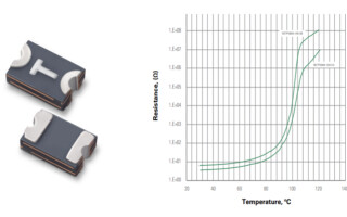
Monitoring temperature protects the USB-C plugs and receptacles from overheating due to dust and dirt accumulating between the narrowly spaced connector pins. The debris can cause a short circuit. If the temperature rise is not detected, a fire could result. Littelfuse offers a unique component, a setP™ temperature indicator, for monitoring the temperature in the plug or receptacle of the USB-C cable. If the monitored temperature exceeds 100 C, the setP temperature indicator will increase its resistance by six (6) decades, causing the power to shut down. As the USB-C power delivery standard recommends, placing the setP temperature indicator in the USB-C Communication Channel ensures overtemperature protection without limiting power output. Figure 5 presents the surface mount component and the characteristic resistance-temperature curves of two eFuse versions.

Figure 5. Temperature indicator for USB-C power delivery circuits (courtesy of Littelfuse)
Maximizing USB-C Efficiency
Consider components that will increase the efficiency of a USB-C charger design and contribute to lower power consumption. In the High-Frequency Converter circuit, select power diodes with low forward voltage and low reverse leakage current. For the Output Protection, Rectifier, and Filter circuit, look for Schottky diodes with low forward voltage drop and a high dv/dt rating to maximize AC-DC conversion efficiency. Schottky diodes are available in packages with a half-bridge rectifier diode pair to save component count.
Only five components provide complete protection for the charger. Combining overcurrent, overvoltage, and overtemperature protection with high efficiency components will ensure a robust and efficient USB-C charger.
Lithium-Ion battery chargers
A second type of charger is specifically designed for Lithium-ion batteries. This type of charger offers more design flexibility since the power output is not limited by a standard. Figure 6 presents an example of a Lithium-ion charger and illustrates the charger block diagram.

Figure 6. Lithium-ion battery charger, block diagram, and recommended safety components
Lithium-ion battery charger protection recommendations
Like the USB-C charger, the Lithium-ion charger obtains its power from the AC power line and is subject to the potential current and voltage hazards on the AC line. A time-lag fuse will provide overcurrent protection. The same guidelines apply to this fuse as the fuse selected for the USB-C charger. Including a metal oxide varistor (MOV) in the Lithium-ion charger suppresses overvoltage transients induced on the AC line. The MOV should be capable of:
- Absorbing between 11 and 360 J of a pulsed energy transient or a current burst between 1200 and 6500 A
- Clamping the transient to a low voltage
- Compliance with UL 1449, Surge Protective Devices.
With TVS diodes, prevent damage to the Rectification, High Frequency Converter, PFC, and Output DC Protection circuits from transient overvoltage and ESD. TVS diodes with similar capabilities to those recommended for the USB-C charger provide a sufficient level of protection.
Maximizing Lithium-ion charger efficiency
A few component additions can significantly impact the efficiency of the Lithium-ion charger. Using efficient MOSFETs enables reduced power loss in the Rectification, High Frequency Converter, and PFC circuit. Consider MOSFETs with low RDS(ON) values to minimize on-state power loss. Also, investigate MOSFETs with low gate charge and high dV/dt rates to minimize switching loss and allow higher-frequency switching in AC-DC conversion.
In the Secondary-Side Rectification and Filter circuit, employ Schottky diodes like those recommended for the USB-C charger. The Schottky diodes minimize power loss in this circuit.
As with the USB-C charger, the Li-ion charger only needs a few components for circuit protection. A reasonable selection of power components can reduce power consumption.
Wireless chargers
The third type of charger offers the convenience of eliminating the charger cable between the charger and the device requiring charge. Wireless chargers defined by the Wireless Power Consortium can have a power level of up to 60 W. The benefits of wireless charging include eliminating the risk of damage to the charger or the load due to incorrect cable insertion or a damaged cable and less wear on charging port connectors. Figure 7 illustrates a wireless charger and shows a block diagram of a DC-powered wireless charger.

Figure 7. Wireless charger with block diagram and recommended components
Wireless chargers protection recommendations
Unlike AC-powered chargers, a fast-acting fuse can protect the DC input circuit from overcurrent conditions. Investigate a fast-acting fuse that will open in under 5 seconds when exposed to a 200% overload above the fuse's current rating. A surface-mount, thin-film fuse package will save printed circuit board (PCB) space.
A fast-acting TVS diode can provide transient overvoltage and ESD protection for downstream circuitry. Look for a TVS diode that can withstand up to 1500 W of peak pulse power or absorb 200 A of peak surge current. The TVS diode should also withstand an ESD strike as high as 30 kV. Use either a unidirectional or a bi-directional component.
If the wireless charger uses the USB-C input power option, a single IC eFuse can protect the USB input from overcurrent, overvoltage, and overtemperature. A setP temperature indicator embedded in the USB-C cable and connected in the Communication Channel circuit prevents short circuit damage to the cable.
Keeping out ESD can ensure the integrity of the USB data lines. TVS diode arrays with an ultra-low capacitance of typically 0.15 pF can minimize disturbance to data line signals. These diodes can also have an ultra-low clamping voltage of under 15 V to protect sensitive ICs.
Applicable Safety Standards
Multiple safety standards govern consumer products such as battery chargers. Table 1 contains the applicable national and international safety standards for battery chargers. Design teams must be aware of and understand the requirements for their products.

Table 1. Worldwide charger safety standards and the Littelfuse components that enable compliance
Recommended components and expert support enable a robust battery charger design
Ensuring the reliable performance of battery chargers is essential as consumers rely on more battery-powered portable products. Protecting battery chargers from electrical hazards such as overcurrent, overvoltage, ESD, and overtemperature is critical for ensuring reliable operation. Design teams can save development time and costs by using component manufacturing expertise. Component manufacturers' application engineers can assist with:
- Appropriate component selection
- Identification of the appropriate standards with which the product must comply,
- Pre-compliance testing services are offered by some manufacturers (such as Littelfuse).
With this article's recommendations and applications engineering assistance, designers can optimize their design for rugged, reliable, and efficient performance. To learn more about emerging circuit protection, sensing, and power control technologies shaping the next generation of battery chargers, visit www.littelfuse.com.
Reference Literature
- Circuit Protection Product Selection Guide
- Power Semiconductor & IC Selection Guide
- How to Select an Appropriate ESD Device
Charger Standards
- USB Implementers Forum, Front Page | USB-IF, USB-C standards, USB Type-C | USB-IF
- Wireless Power Consortium (WPC), Home | Wireless Power Consortium, Qi® 1.3 Wireless Charging Specification, Qi Wireless charging | Wireless Power Consortium
Prasad Tawade is a Strategic Marketing Manager for the Electronics Business Unit of Littelfuse. He manages go-to-market strategy for new products and develops monthly application spotlights and distribution marketing initiatives. Prasad joined Littelfuse in December 2018 during the acquisition of IXYS, where he was the EMEA Distribution Sales Manager. Before IXYS, he worked as a product manager at Pericom Semiconductor and Cypress Semiconductor. Prasad holds a bachelor's degree from Pune University in Electronic Engineering and a Master of Engineering Management degree from Duke University.

Prasad Tawade is a Strategic Marketing Manager for the Electronics Business Unit of Littelfuse. He manages go-to-market strategy for new products and develops monthly application spotlights and distribution marketing initiatives. Prasad joined Littelfuse in December 2018 during the acquisition of IXYS, where he was the EMEA Distribution Sales Manager. Before IXYS, he worked as a product manager at Pericom Semiconductor and Cypress Semiconductor.